In Midwest fab shops, I see the same pattern: the laser runs fast, but the real schedule risk shows up at the brake when “good parts” suddenly need handwork. The bottleneck is almost always the handoff from CAD to CAM to the press brake, especially when programmers, operators, and engineering are working from slightly different assumptions. When that happens, you pay for it in rework loops, extra setups, and downtime risk that is hard to forecast and harder to recover.
Why Laser Cut Parts Fail at the Brake and Where Rework Starts
Most brake problems start upstream: a flat pattern that “looks right” still fails when bend allowance, K factor, or inside radius assumptions differ between CAD, CAM, and the brake’s bend tables. On the floor, it shows up as parts that are long or short at the flange, holes drifting into bend zones, and operators chasing dimensions with extra hits or shims. That turns one clean forming step into multiple touchpoints and minutes per part that multiply across the job.
The practical fix is to treat laser-to-brake as one workflow, not two departments. Standardize the bend model (material, thickness, tooling radius, bend method) and push the same calculation logic through CAD, flat pattern generation, and brake programming so the first article fits without “operator math.” When this is aligned, shops routinely cut first-article troubleshooting from hours to minutes and reduce scrap and rework that used to get baked into every repeat order.
Hidden Misalignments Between CAD, CAM, Nesting, and Bend Deduction Tables
A common hidden misalignment is that CAD exports a DXF flat that’s already “bent” mathematically, while CAM applies its own bend deduction assumptions or the brake program uses a different bend table. Another is when nesting rotates parts without preserving grain direction or bend orientation rules, which changes forming behavior and cosmetic outcomes. Even small differences across shifts or programmers become large when you’re bending long flanges or stacking tolerances on multi-bend parts.
Common failure points:
- CAD bend allowance uses a different inside radius than the brake tooling actually installed
- CAM re-creates flats from 3D with default K factors that differ from engineering standards
- Nesting rotates parts and breaks grain direction rules for stainless or aluminum
- Brake uses legacy bend tables not tied to current material certs and thickness callouts
The fix is to define a single source of truth for bend deductions and lock it into templates and post processors. In Mac-Tech installs, the “real work” is not just software loading; it’s confirming what your brake actually produces with your punches/dies, then calibrating tables and permissions so the whole chain uses the same numbers. The outcome is repeatability: fewer “tribal knowledge” overrides and faster onboarding because new programmers and operators aren’t guessing which table is “the good one.”
CAD CAM Setup Checklist for Consistent Bend Deductions and K Factors
If you want first-time fit, your bend math must be consistent and test-backed. That means validating bend deductions with real coupons for each material/thickness/tooling family, then freezing those results into controlled libraries used by CAD and by brake programming. The goal is to stop re-deriving K factors job by job and start producing stable outcomes across shifts.
Setup checklist:
- Build bend tables by material, thickness, and tooling radius, verified with physical test bends
- Standardize bend method (air bend, bottom, coining) per family and lock it in templates
- Require a single flat-pattern generation method (CAD-driven or CAM-driven), not both
- Tie part properties to tables: material spec, thickness, grain direction, and finish requirements
When shops do this, they typically eliminate the “2nd program” at the brake and reduce setup time because operators aren’t compensating for inconsistent flats. You also get measurable quality gains: fewer out-of-tolerance flanges, better hole-to-bend location control, and less inspection sorting on multi-bend parts.
Nesting and Cut Strategy Controls That Preserve Bend Zones and Edge Quality
Even with perfect bend math, cut strategy can sabotage forming. Heat input, edge taper, micro-joints, and lead-in placement all affect bend consistency, especially near tight radii or cosmetic faces. Nesting that ignores bend zones can also place common-line cuts, tabs, or skeleton supports where the brake needs clean material behavior.
Controls that matter:
- Keep lead-ins/lead-outs and micro-joints out of bend zones and cosmetic edges
- Enforce grain direction rules and lock rotation constraints for formed parts
- Set edge quality parameters (gas, speed, pierce strategy) by material and thickness family
- Define no-go zones near bend lines for marking, etching, and part ID features
The fix is to make nesting rules part of the forming standard, not a programmer preference. When nesting is constrained to protect bend zones and edge quality, shops see fewer cracked bends, less deburring time, and more predictable brake tonnage and springback, which shortens changeovers and stabilizes throughput.
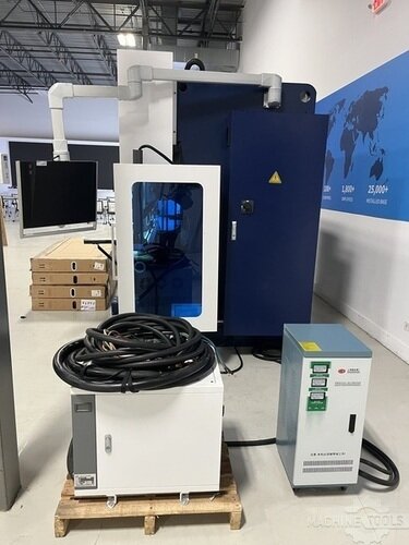
HSG HC1703
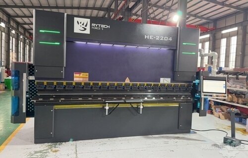
RYTECH FORCE-1 HE 2204
Revision Control and Change Management to Keep Cut and Brake in Sync
Revision drift is one of the most expensive forms of rework because it looks like a forming problem when it’s really a data problem. A small hole move, a bend angle tweak, or a tolerance change can land in CAD but not in the CAM program, or it gets cut correctly but the brake still runs an older bend sequence. On the floor, you feel it as “mystery nonconformance” and urgent remake requests that interrupt scheduled work.
The fix is disciplined revision control: a controlled release process where the laser program, nest, and brake program are all regenerated or verified from the same revision, with clear status labels and archived traceability. This is where integration and training matter in real life; at Mac-Tech we often help shops map who owns approvals, where files live, and how to prevent “local copies” from becoming production. Done right, you reduce remake events, shrink ECO cycle time, and protect uptime by preventing bad data from entering the queue.
Next Steps for Modern Fabricators to Build a First Time Fit Workflow
Start by auditing your last 20 rework tickets and tagging the root cause as bend math, nesting strategy, tooling mismatch, or revision drift. Then pick one high-volume material family and build verified bend tables, standard templates, and nesting rules that can’t be bypassed without approval. This phased approach usually produces results quickly because you’re fixing the repeat work that consumes the most capacity.
If you’re evaluating upgrades, focus on software compatibility, post processor control, and how easily you can enforce standards across programmers and shifts. Practical resources and tooling to support a tighter workflow are available at https://shop.mac-tech.com/, and if you want to explore connected quoting to production data flow, https://vayjo.com/ can be a helpful reference point for reducing handoff friction. The measurable outcome to target is simple: fewer touchpoints per job, shorter first-article time, and a repeatable process where the brake runs what the laser intended without manual corrections.
FAQ
How fast is the ROI on aligning laser-to-brake workflow?
Most shops see payback in months, driven by fewer remakes, faster first-article approval, and reduced setup time per job.
How long does training take for programmers and brake operators?
Typically days to get productive on the standardized workflow, and a few weeks to fully normalize libraries, templates, and revision discipline across shifts.
Can we retrofit this process or do we need all new machines?
You can retrofit most of it through software standards, bend table validation, and controlled revision processes, even with existing lasers and brakes.
Will this work with multiple CAD and CAM packages in the same shop?
Yes, but only if you pick one source of truth for bend deductions and enforce consistent export/import rules and posts across every seat.
What’s the uptime risk while we change tables and posts?
Managed rollouts keep risk low by validating on coupons and pilot part families first, then expanding once the results are repeatable.
How do we keep changes from drifting back to old habits?
Lock standards in templates and permissions, add release checkpoints, and track rework causes so you can correct the process instead of blaming the brake.
If you want to walk through your current laser-to-brake bottlenecks and what to standardize first, email me at aquoss@mac-tech.com or connect via https://shop.mac-tech.com/contact/.
Get Weekly Mac-Tech News & Updates